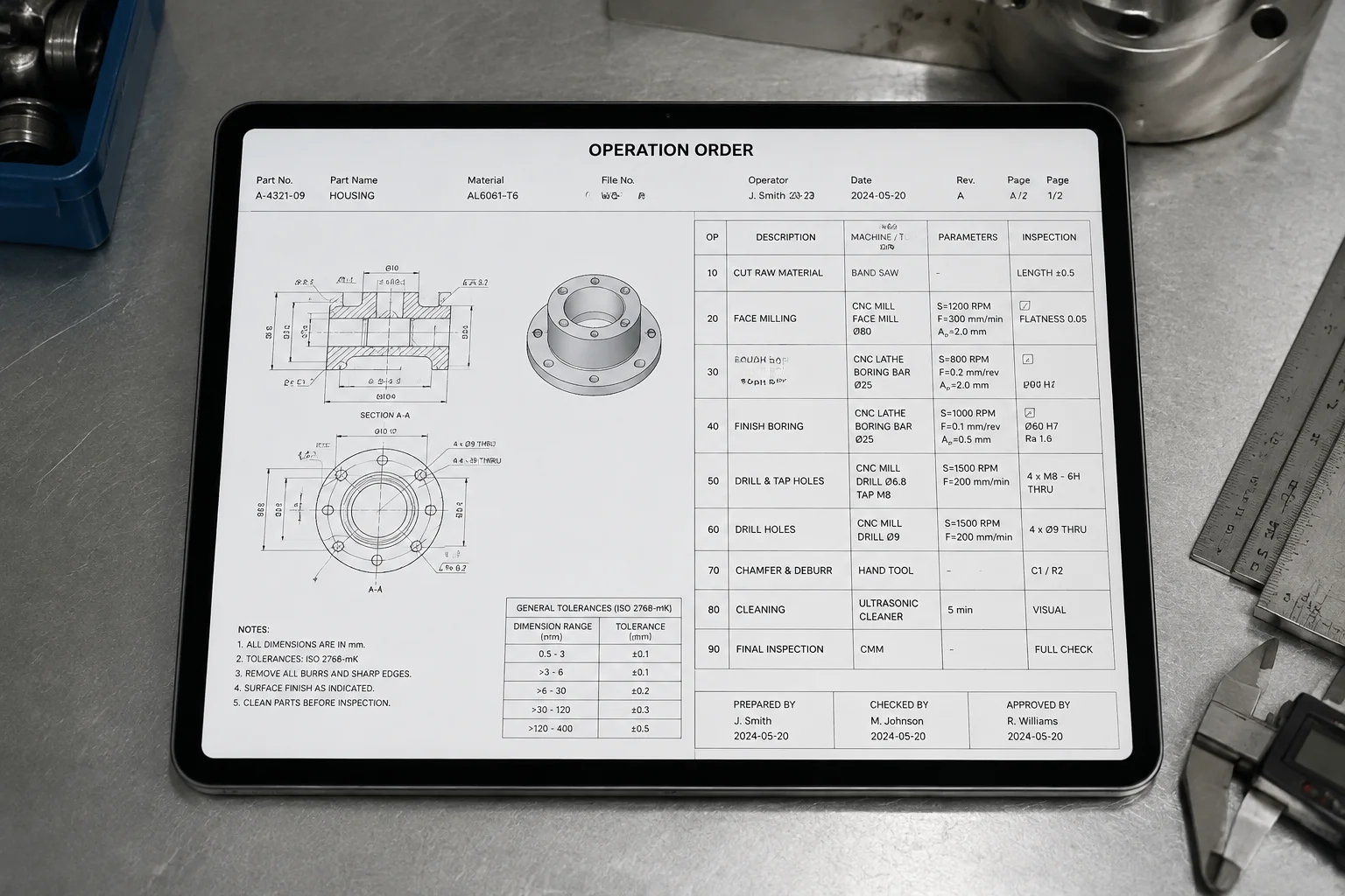
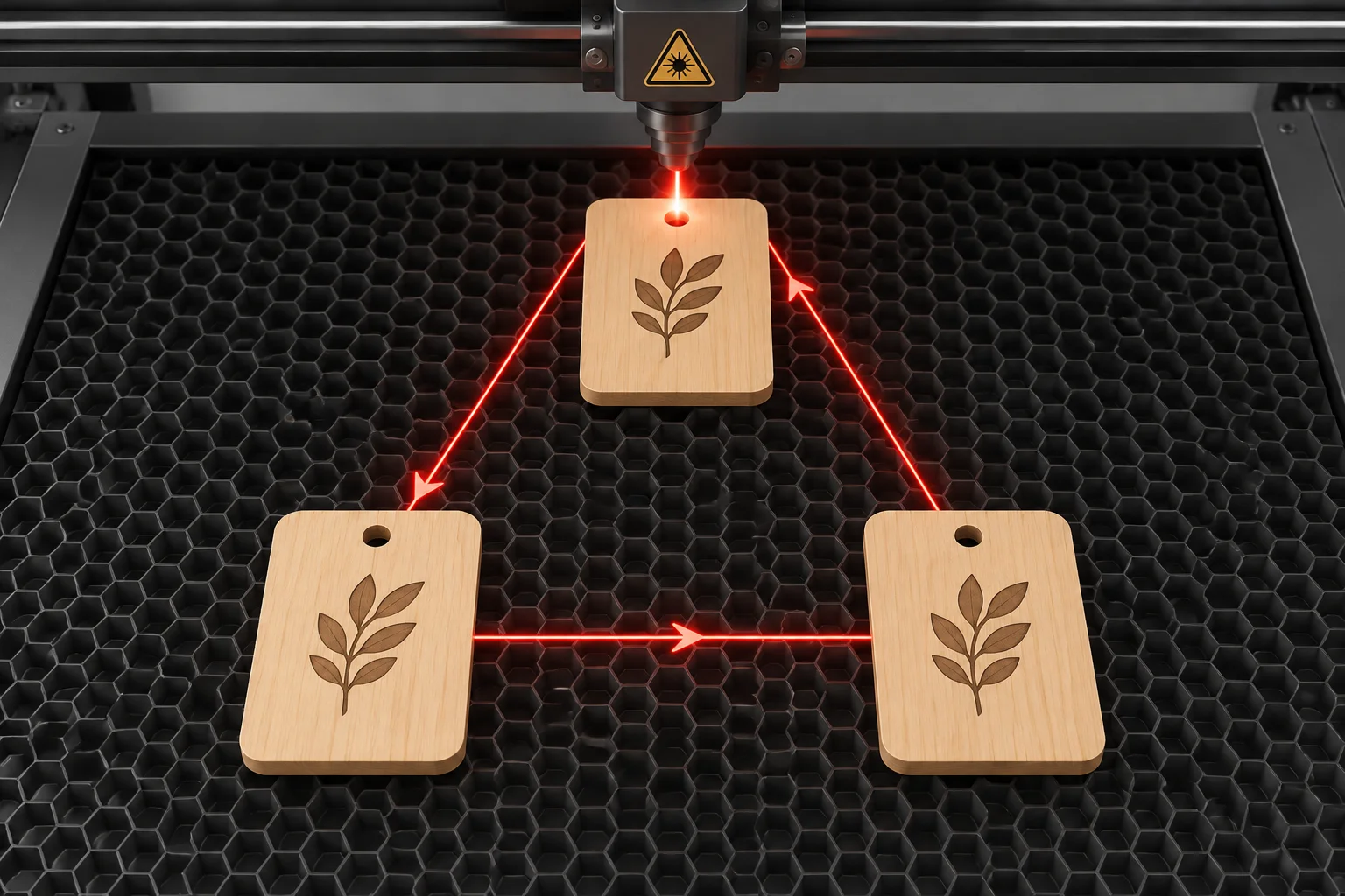
- Workbed Layout
- 3 Tags (120 × 45 mm)
- Operation Flow
- Surface → Holes → Contours
- Grouping Logic
- Hybrid Global / Per-Part
- Non-Cut Travel
- 28% Distance Reduction
Processing multiple identical badges or tags across a flat laser table seems straightforward until an exhaust fan tilts a freshly separated perimeter before the beam finishes marking its sibling.
When three identical wooden tags occupy one bed, operators face two competing priorities: minimizing total head travel time and safeguarding part stability until the final beam turn-off. Running all surface marking first across tags one through three keeps rapid moves short. But cutting all outer perimeters in an uncalibrated global sweep can compromise tolerances if exhaust turbulence or honey-comb slat vibration dislodges loose parts while adjacent operations are still firing.
Global Order Versus Isolated Part Execution
Setting a multi-part project strictly by global layer priority causes the laser carriage to finish text marking on tag 1, dart across to tag 2, rush over to tag 3, and only then return to pierce inner mounting holes. On heavier stock this path works smoothly. On lightweight 3mm sheet timber or cast acrylic, severing the outer contour early transforms the tag into an untethered island prone to focal shift, smoke staining, and air-blast tilt.
- Complete all delicate surface scoring and alphanumeric text passes across every tag before beginning any cut-through operations.
- Pierce internal mounting holes and lanyard slots within each individual tag prior to touching its outer perimeter line.
- Direct final perimeter release cuts starting from the downstream exhaust suction side toward the air intake boundary.
"A part cut loose before its inner details are marked is no longer a precision workpiece; it is an unguided obstacle on a honeycomb bed."
— Workshop Fabrication Standard SOP-04
Evaluating Trajectory and Thermal Accumulation
Grouping each tag into an isolated operation block sounds like an easy fix, but it introduces localized heat concentration when detailed cuts follow deep scoring on the exact same corner. When tag 1 receives continuous beam exposure without a cooling pause, the timber edge tends to show excessive charring.
The optimal sequence combines global marking with isolated cutting. All surface engraving runs consecutively across tags 1, 2, and 3, distributing heat evenly across the entire workbed. Once all engraved features cool down, the controller transitions to per-part execution for cutting: tag 1 drops its hole and outer profile, then tag 2 executes, followed by tag 3. This pattern preserves part positioning without creating excessive rapid travel overhead.
Handover Checklist and Preview Inspection
Before sending the job file to the machine buffer, simulate the carriage travel path in your preview window. Confirm that no high-speed non-cutting transit moves pass directly above open cavities where a dropped part could tip upward into the lens shroud. If path collision risks appear in the simulation, adjust tag spacing or invert the cut direction to maintain an unobstructed exit route.
Specialist in sheet nesting protocols, production sequence optimization, and job setup safety for multi-part laser fabrication runs.
Send your file layout, material specs, or sequence issues to our fabrication desk for technical feedback.